|
Lots of people end up acquiring their PC-8300 from eBay. And a lot of them being sold had
previously been used for some type of industrial application (label printing, factory
machine control, etc) where the original 128K masked system ROM had been swapped out for a 32K
EPROM which had a properietary single-use application. These PC-8300s are essentially
crippled and aren't capable of doing anything other than the industrial application. But the original NEC PC-8300 system ROM is a 28-pin 128K masked ROM, meaning the contents were programmed via an IC circuit fabrication process. Restoring an industrial-style PC-8300 back to its original purpose is not as simple as just finding a 28-pin 128K EPROM chip and programming it. There just isn't a matching 28-pin 128K EPROM for the the chip that NEC used. It just doesn't exist! What people usually do is find a 32K image for the PC-8201A system, and burn that into a 32K EPROM which they plug into the system ROM socket. This works well, but you now have a PC-8300 that behaves like the original 8201A, and it lacks the enhancements to TEXT and TELCOM that the PC-8300 gets from the extra 96K of system ROM space that it has over an 8201A. But now, there is hope for anyone wanting an original 128K system image for their PC-8300. There are a couple of 32-pin EPROMS that have a pinout that has matching address and data lines. This means that it is "almost" compatible with the 28-pin socket in an 8300, there's just some extra pins that have to be dealt with. And, there is a way to deal with those extra pins! There is now a way to use a 32-pin EPROM and plug it into a 28-pin system ROM socket in the NEC PC-8300 and have the full 4-bank of 32K ROM images represented, where the functionality of the original machine is completely available to you. Compatible EPROMS: NEC 27C1000 & HN27C301G. Those are the ONLY chips you can use. They are 32 pin 1M EPROMs but are pin compatible with 28 pin 1M uPD231000 mask ROM. 1. Burn your 128K ROM image into the suitable chip. 2. Solder a jumper wire connecting Pins 1&2 (Vpp and OE) together and to Pin 16 (GND). 3. Solder the not-connected Pins 31&32 (/PGM & Vcc) together and to pin 30 (NC) to pick up VCC from the 28-pin socket below (ie 30&31&32 together). 4. Insert correct orientation in ROM 0 socket, leaving Pins 1&2 and 31&32 of the EPROM hanging out in mid air near the bottom edge of the computer. The following is a diagram of the original PC-8300 28-pin masked ROM, and the way you will be wiring your 32-pin EPROM for use in the 28-pin socket: |
MASKED ROM                            EPROM
(1M) 128k x 8 mask rom (TC531000)     (1M) 128k x 8 EPROM (HN27C301 or NEC 27C1000)
(23C1000)
                                    / Vpp    +-v-+ 32  Vcc   \
                                   |\ OE   2 |   | 31  PGM/ -|  <-- Wire pins 32, 31 and 30
A15  1 +-v-+ 28  VCC               |  A15  3 |   | 30  nc    /      together, getting Vcc
A12  2 |   | 27  A14               |  A12  4 |   | 29  A14          from pin 28 of socket.
A7   3 |   | 26  A13               |  A7   5 |   | 28  A13
A6   4 |   | 25  A8                |  A6   6 |   | 27  A8
A5   5 |   | 24  A9                |  A5   7 |   | 26  A9
A4   6 |   | 23  A11               |  A4   8 |   | 25  A11
A3   7 |   | 22  A16               |  A3   9 |   | 24  A16
A2   8 |   | 21  A10               |  A2  10 |   | 23  A10
A1   9 |   | 20  CE/               |  A1  11 |   | 22  CE/
A0  10 |   | 19  D7                |  A0  12 |   | 21  D7
D0  11 |   | 18  D6                |  D0  13 |   | 20  D6
D1  12 |   | 17  D5                |  D1  14 |   | 19  D5
D2  13 |   | 16  D4                |  D2  15 |   | 18  D4
GND 14 +---+ 15  D3                 \ GND 16 +---+ 17  D3
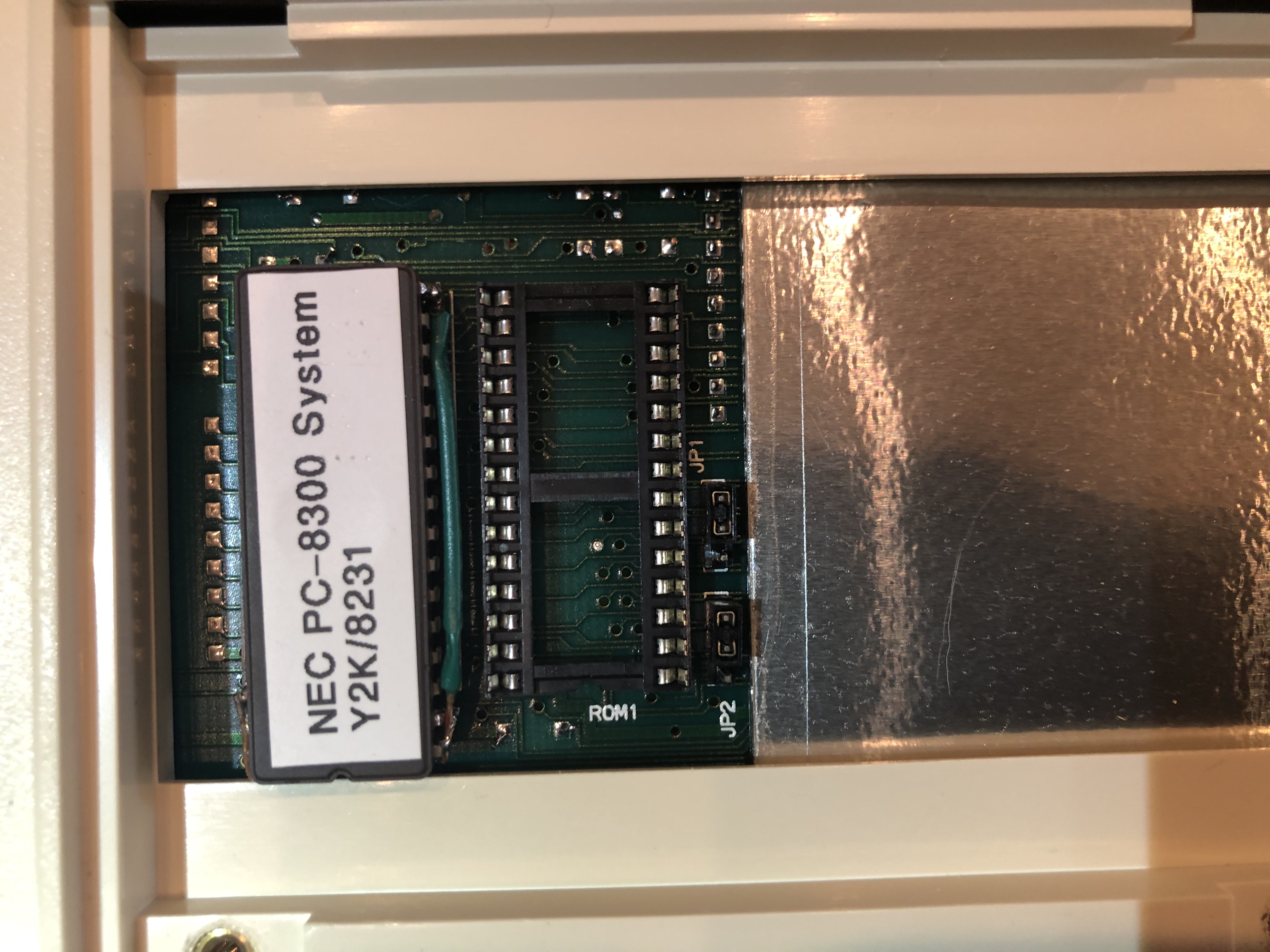
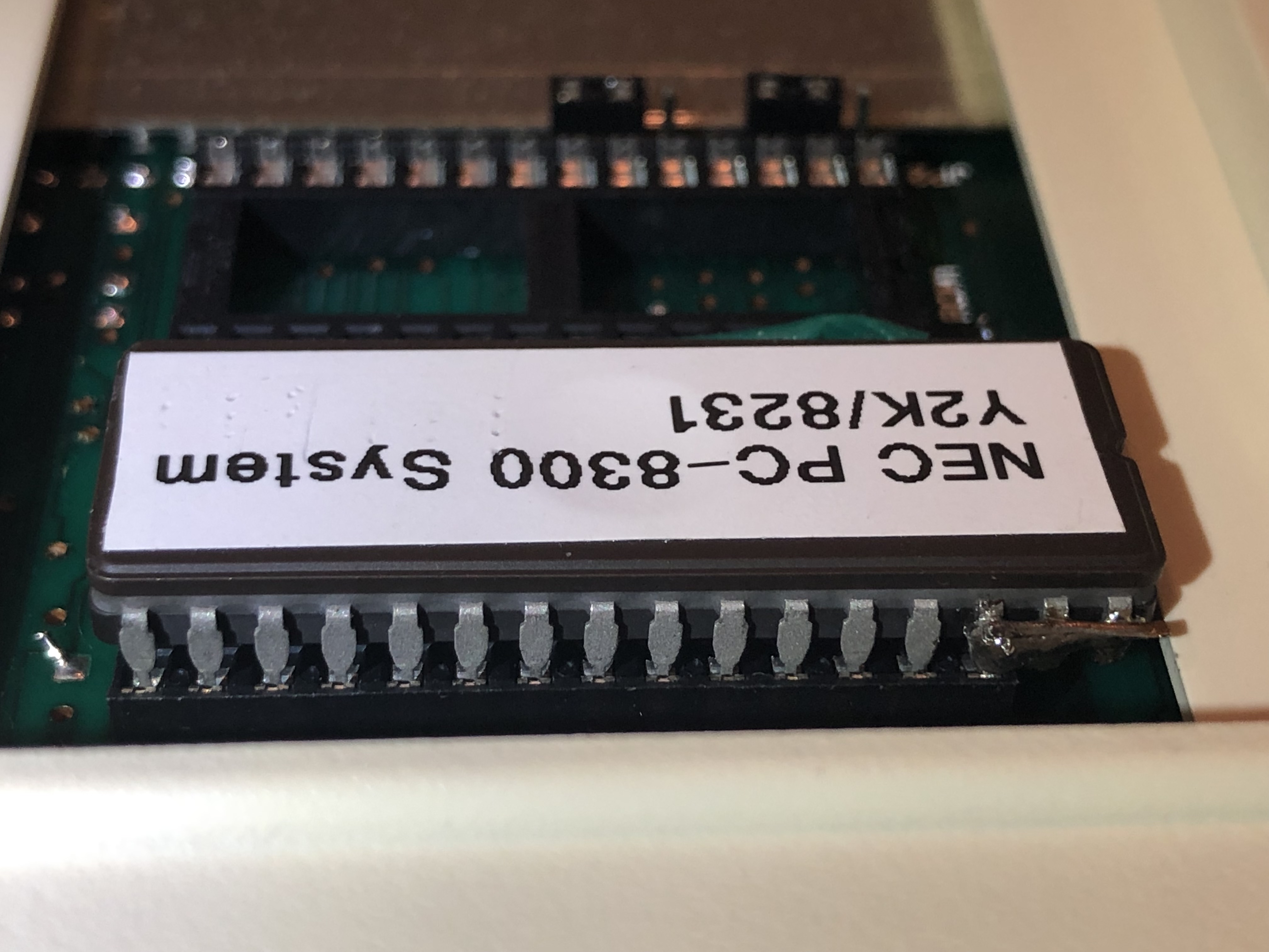
Here's some images to illustrate the solution in a PC-8300: